
Job Description
The hockey stick bench is a great piece of fully functional furniture that doesn’t require a lot of sticks. Composite sticks are really strong, so even if you space them out, they make a good seat. This design will give plans for using sticks for the legs and pucks for the feet, adding an extra “cool” factor. Though the hockey stick bench legs are at an angle with this design, it can be easily modified for the legs to be perpendicular to the seat, making it simpler to build.
Materials Required:
- Mitre Saw
- Router or Mill
- Drill
- Allen wrenches
- Wrench set
- Bubble level
- 4 bar clamps (2 greater than 3 ft)
- Several 2″ spring clamps
- Glue
- 14 hockey sticks
- 8: 5/16″-18 Shoulder Bolt, 2.75″ long
- 8: 5/16″ Washer
- 8: 5/16″ Nuts
- 4: #10-32 Shoulder Bolt, 2.5″ long
- 4: #10 Washer
- 4: #10-32 Nuts
- 8: #6 1.5″ Sheet metal screw
- 27: #6 1.25″ Sheet metal screw
- 4: 3″ Mending plates (if reinforcement desired)
- 16: #8 1/2″ socket cap screws (if reinforcement desired)
Build the seat
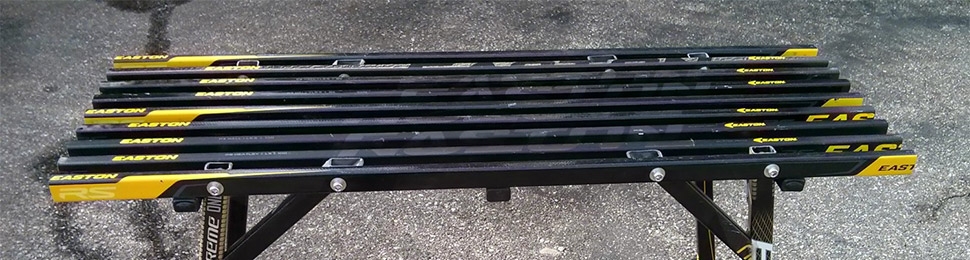
The first order of business is the seat. You’ll want to use only those sticks that are greater than 41.5″ in length. Don’t try to glue or attach broken sticks together to try to get the length right. It’s for a bench, so you don’t want to sit down and have the seat break!
First, cut nine sticks to 41.5″ length. Then cut three seat attachment pieces to 12.75″ in length and in two of them, drill holes of about 7/32″ in diameter 3.75″ inches from either end. Choose four of the nine seat slat sticks and drill 3/8″ holes in the locations shown in the image below. (Note: image does not show the other seven sticks.)
Using spare sticks or other material as spacers, clamp all nine of the 41.5″ sticks together where two of the sticks with the holes should be on both outer edges. Secure the seat attachment pieces on the bottom of each stick as shown in the images below using #6, 1.25″ sheet metal screws ensuring the two bench attachment pieces with holes are on the outside. For the #6 screws, I recommend drilling a pilot hole with a 7/64″ bit to make driving the screws much easier. The spare sticks are highlighted orange in the image below.
Go ahead and remove the spare sticks in between, and you’ve got a bench seat!
Building the legs and leg supports
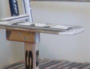
The three pieces for a single leg are shown in the image below: an approximately 18″ leg, a 10 13/16″ support piece and a small 4.5″ support piece. You’ll have to make four of all three pieces.
Take the main leg and the longer support pieces and insert them between the first two bench slats as shown below. The leg face with the 10 degree angle cut should face down on the bench so the leg angles outward. The support piece should have the 45 degree cut face down between the bench slats, putting the 55 degree cut against the leg.
Using two 5/16″ to 18 2.75″ shoulder bolts, bolt the legs and the supports pieces to the bench. Be sure to use a washer behind the bolt head and nut. Next, drill a #6 1.5″ sheet metal screw and a #6 1.25″ sheet metal screw from the support piece into the chair leg. The 1.5″ screw should be on the inside, since it has farther to travel. The drawing below summarizes the connections that should be made for each leg at this step. Repeat this process for all four legs.
First, measure the distance between legs on a short side of the bench down the seat starting at the outer edge of each leg. It should be approximately 11.25”. Clamp a temporary brace between the same two legs near where the feet will go. Doing so makes sure your legs will be vertical when we add this final support pieces and not tilted inward or outward.
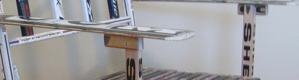
Now that the legs are vertical, slide the small support pieces into their anticipated locations, with the 55 degree face down on the bench slats and the 35 degree face on the legs. Using a 7/32″ drill bit, slide it through the seat attachment piece holes and twist it, marking the small support piece beyond with a small divot. Marking the drill point this way eliminates any wander from making a circle with an inserted pencil. Since you used a 7/32″ drill bit to make the hole, it should fit right in and be nicely centered. Do this for all four legs.
Remove the small support pieces and using each divot as a guide, drill through them with the 7/32″ bit. Returning the small support pieces to the bench, you can run #10-32 bolts through both pieces and seat attachment pieces as shown below. Again, make sure you put washers on both the head and the nut of the bolt.
Holding each support piece in place, drill in a #6 1.25″ sheet metal screw.
You should have legs that look similar to the bench below.
It’s time to reinforce the leg joints. You should notice small gaps between the leg support pieces and the legs. In the picture above, it’s right above the S on the leg. Fill in these and all other gaps using a very high-strength adhesive such as epoxy. You can buy lots of different types of epoxies from generic hardware stores. A general-purpose epoxy will do if it’s an indoor bench. The biggest difference will be the cure time but very generally speaking, the longer the cure time, the stronger the bond.
Optional step: You can choose to add additional reinforcement to the leg/leg-support-piece junction by incorporating a mending plate.
Puck feet
Puck feet add a great final touch to the bench, so I recommend adding them; however, they are not for the faint of heart and you’ll need a router or end mill to do it. Remove the puck material about 1/2″ down on the inside part of the puck, since that will be where the longer portion of the stick inserts. Measure each leg’s cross section dimensions (1-3/16″ x 0.75″ or so, depending) and undersize the hole in the puck by about 1/32″ (this depends on the puck hardness). This will allow the stick to compression fit into the puck. If your hole is accidentally too large, you can epoxy the stick into the puck.
Once you’ve routed or milled out all four puck feet, push them on and you have your bench!
Check your provincial and municipal codes before starting any project. Follow all safety precautions. Information in this document has been furnished by the North American Retail Hardware Association (NRHA) and associated contributors. Every effort has been made to ensure accuracy and safety. Neither NRHA, any contributor nor the retailer can be held responsible for damages or injuries resulting from the use of the information in this document.
